ROADS & BRIDGES
Strengthening of girder beams with External Post Tensioning
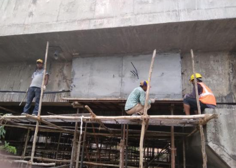
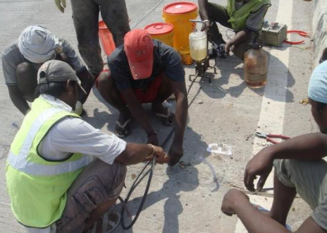
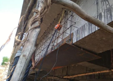
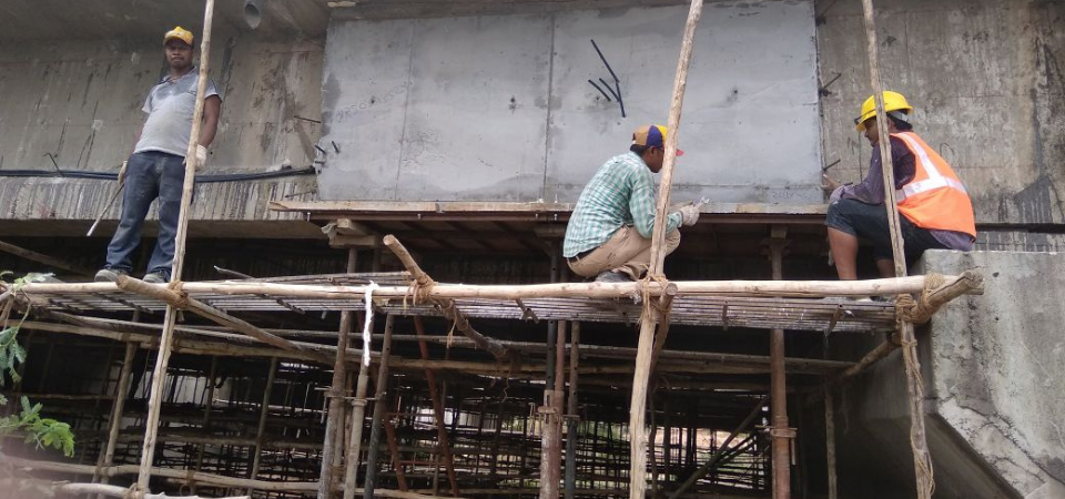
The poor quality of concrete resulted in the sagging of the pre-casted RCC girders of a bridge. Strengthening of girders was carried out by way of epoxy injection grouting, micro-concrete encasement with external PT cables.
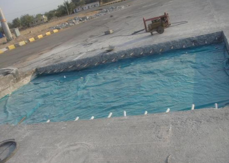
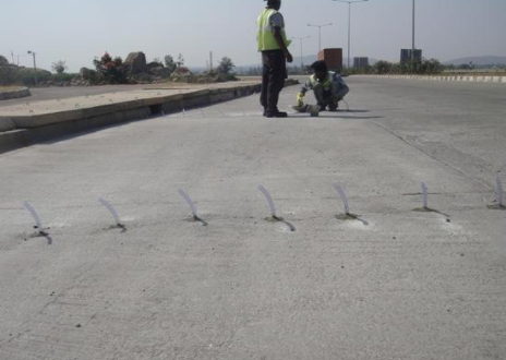
Repairs to PQC road
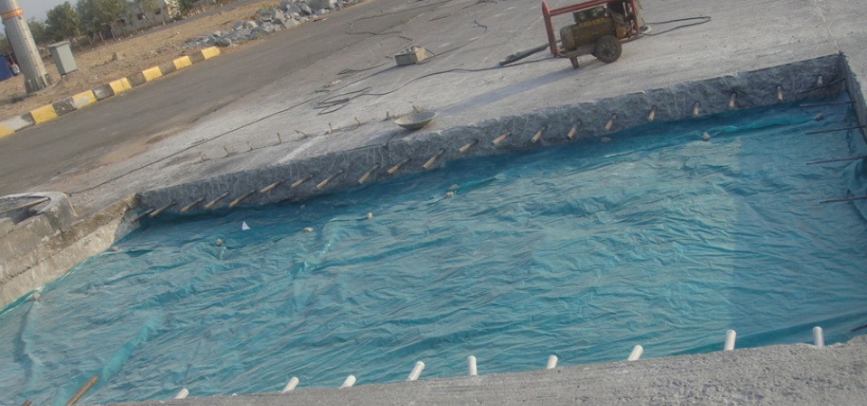
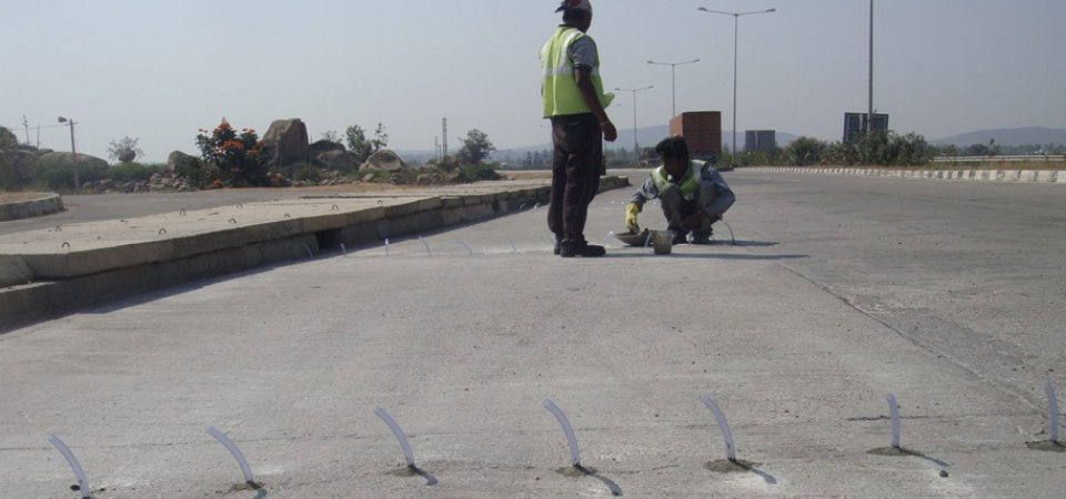
The cracked PQC road panels were repaired by stitching method as per IRC code provisions. The severely damaged panels were re-casted with high grade micro concrete
Pier Tilt Correction at Jammu & Kashmir
In an under construction project in Jammu & Kashmir, a Bridge Pier of (22m height) got tilted due to scouring of the sub-soil beneath the structure.
For further progress of work, the pier had to be either dismantled & re-constructed or pier tilt to be corrected and placed in position. The client, after consulting several agencies/contractors, approached Varshitha for suitable solution which was successfully executed and the work was acclaimed by client.
Restoration of a 45 year old PSC Bridge By External Post Tensioning
PSC bridge across TUNGABHADRA RIVER was constructed in 1968 and in service since then. As part of the 4 lining of Highway between Hungund and Hospet towns of Karnataka State, it was proposed to construct parallel bridges of 2 lanes at KM 291 & 292 on the downstream of Tungabhadra Dam and investigate the suitability of the existing bridges for use for the two lanes.
VARSHITHA was awarded the contract of detailed Non-Destructive testing and Design of Restoration Scheme for the bridges. Detailed ND Tests were conducted & Design analysis were carried out on the superstructure and it was concluded that the existing 19 span & 16 span structures are suitable for present day traffic and design consideration. However in each of the bridge damage in form of exposure of PT cables/snapping was observed in the end girder (in 7 spans of each of the bridge). In view of the same restoration measures were carried out to the 7 spans in each of the bridges using external Post-Tensioning Technique. Being a structure with active stresses it was prudent to use Post Tensioning technique as a passive strengthening technique would not have been very effective for active structure.
Restoration of a failed Bridge
This case refers to a bridge which had completely failed in service. The bridge was a single span T beam slab bridge with 3 nos Beams and is located on a very important connecting road between National Highway 7 and National Highway 9, about 75 KM from Hyderabad.
One fine day the bridge suddenly failed by developing major vertical cracks in all the 3 beams in the centre and the deflection was observed to be about 220 mm. The main cause being
a) Poor quality of concrete especially in the bottom region of the beam
b) Overloading of the structure. (Vehicle load more than designed capacity)
It was a clear failure of the structure and in normal cases the best option would be to re-construct the superstructure. However, the process involved in re-construction would take about 3-4 months starting from budget sanction to floating tenders and final completion of job. The road couldnot be blocked for such long period with very high inconvenience to heavy vehicles which use this road as the main link between the National Highways.
In view of the same, restoration of the structure was awarded to M/s Varshitha to complete the project in less than 1 month. The restoration process involved :
a) Lifting the beams and correcting the deflection.
b) Removing the poor concrete at the bottom region of the beams
c) Replacing the same with Micro Concrete.
d) Providing PT strands in the new encasement and stressing
e) Lifting and replacement of neoprene bearings.
As a first step, bed concreting was carried out at the locations where lifting supports were proposed to be placed to provide a firm base for the supports.
Dismantling of ROB at Nagpur
The Railway over-bridge structure was a 21 span RCC bridge structure across the railway track near the Nagpur Railway Station (Maharashtra). It was proposed to construct a parallel new Cable Stay bridge at the location. In view of the high traffic zone, it was proposed to construct one carriage way cable stay bridge and after dismantling the existing bridge to construct the 2nd carriage way.
The structure being a bridge over the electrified AC OHE lines with very high railway traffic, a safe and economical method was contemplated to dismantle the structure with minimum disturbance to the railway traffic in particular and public in general.
The sequence of execution was as follows :
Dismantling of Parapet Wall
Dismantling of Cantilever Slab
Removal of Wearing Coarse
Saw Cutting of slab between beams & end cutting
Dismantling of Piers
It was proposed to cut the deck slab longitudinally between the beams to cut each slab in 12 pieces (longitudinal). Each T beam piece was then lifted and disposed off using an Over Head gantry. The required gantry duly designed to carry each girder weight of approximately 18.0 to 20.0 MT was fabricated and erected on the deck slab. This gantry was an inverted “U” shaped gantry for easy lifting and hauling of the beam on to next span.

